A script is built up by connecting nodes and macros in a flowchart. The linking arrows determine the order in which the nodes are executed. Multiple paths from a node indicate the possible output decision branches that can be taken. On execution, the script starts at the Start node and executes the nodes in the order determined by the connecting arrows, taking the output path determined by the processing in each node.
The following sections describe:
| • | working with nodes - in particular how to insert, select, delete, cut, copy, paste, and drag and drop them; |
| • | working with paths - in particular how to add, edit, and delete a path; |
| • | other editor functions - particularly undo, redo, and passing data between nodes; |
| • | global properties - particularly adding a script property, using a global property in a node, and exposing properties to the user; |
| • | changing announcements in an Invex system; |
| • | Using CLIPboard elements - including how they are passed to a node; |
| • | Debugging routing scripts. |
Nodes from the node list pane can be placed into the flow of a chart. Once a node is inserted into a chart, new output paths can be created into which more nodes can be inserted. Nodes in a chart may be cut, copied and pasted, as well as dragged and dropped within a chart and between charts.
There are a number of groups of nodes within the node list pane that contain all the nodes and custom macros available for your script creation. The node selected in this pane determine the behaviour of the mouse when in the chart. The insertion point for a node in a flowchart is the arrow that joins two existing nodes.
Nodes can be dragged from the node list pane on to an insertion point in the chart.
Inserting a node
To insert a node, choose the node you wish to insert by clicking the icon in the toolbar. Right click on the arrow at the point at which you wish to insert the node. Select the Insert <Name> from the list.
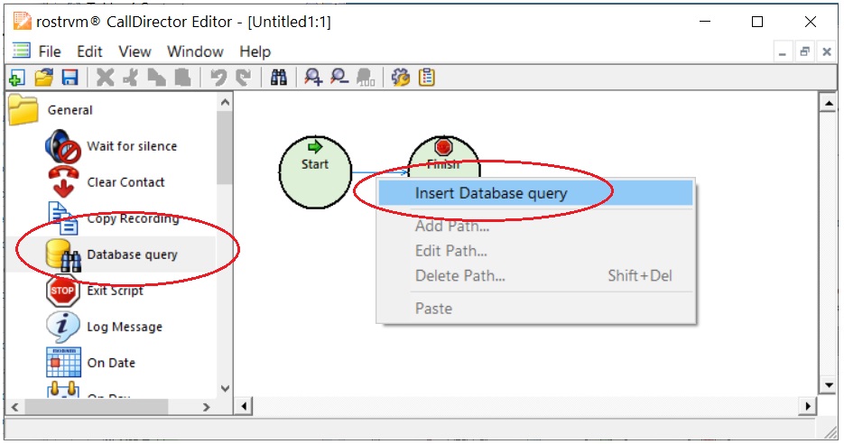
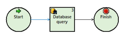
The new node appears, splitting the arrow insertion point.
Node selection
To perform an operation on a node in a chart, you must first click the node to select it. Only a single node may be selected at any one time. As the mouse hovers over a node, it shows focus by highlighting its border. When selected, the node is highlighted:
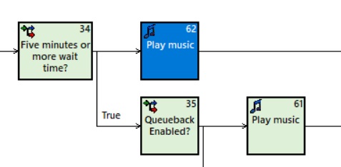
Where a node has a number of output paths, any nodes in those paths become secondary selections and appear highlighted with the primary selection:
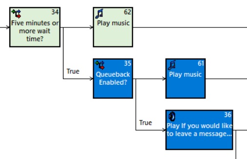
The primary selection becomes the focus for Property Sheet, if it is visible. The entire selection, primary and secondary is subject to all cut/copy/paste/delete operations, as well as drag-and drop. These operations are discussed in the next sub sections.
Deleting, cut, copy, and paste
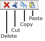
To delete a node, select it as described above and then click the Delete button from the toolbar menu (or simply hit the Del key on your keyboard).
The Cut operation works in a similar way to delete, but in this case the cut selection is placed into the paste buffer. The Copy operation is similar again except that the selection remains in place and a copy is placed in the paste buffer.
Once a cut or copy operation has taken place and a selection is available in the paste buffer, it is possible to paste the selection into any open chart. Rather like inserting a node, an arrow must be chosen as the insertion point for the selection. To select an arrow as an insertion point, click the arrow. At this point the Paste toolbar button becomes enabled. The paste procedure can be repeated as many times as you like, as the paste buffer remains intact until another cut or copy operation replaces it.
Dragging and dropping
A selected node can be dragged to another part of the chart, in order to copy or move it. The choice of copy or move is determined by whether the CTRL key is depressed when the drop occurs. Like cut, copy and paste, both primary and secondary selections - that is, the selected node, all its output paths and the nodes in those paths, are placed into the drag buffer. To begin the drag operation, move the mouse over the primary selection and hold down the left mouse button. The standard No Entry cursor is shown in all places where the selection cannot be dropped. The selection can be copied over any arrow, in any chart. If you are performing a move operation (by holding down the CTRL key) the drop will be barred from any arrow within the selection itself.
Collapsing and Expanding
In order to aid readability, loop nodes or nodes with multiple output paths can be collapsed down to a single node, depicted with a stack of nodes behind it.
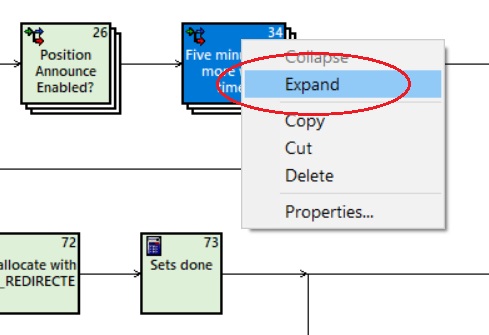
This can be achieved by right clicking on the primary node and selecting the Collapse option. The Expand option can be used to reverse this and display the secondary selection
When placed in a chart a node will simply connect itself to the preceding node and the following node determined by where you insert the node. On execution, control will pass from one node to the next along the joining arrows. Some nodes, however, allow a decision to be taken depending on the result of the execution of a node. For instance, an On Day node could determine the current day and allow the user to perform different processing based upon the result. This is achieved by allowing a node to have more than one output path. You can set up as many outputs as there are variations of the result - for On Day, this would be one for each day of the week.
Adding a path
The following example shows how to establish weekend and weekday processing with the On Day node. The On Day node is inserted into the chart as described in the Inserting a node section above. Right click on the output path of the On Day node. The context menu appears as shown:
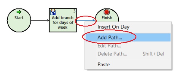
Select Add path ... to display the dialog box for configuring a path.
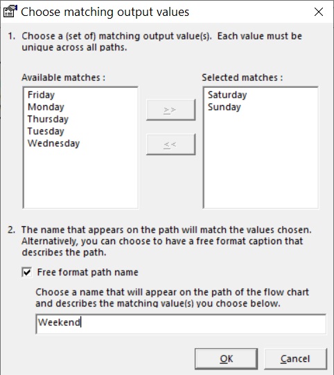
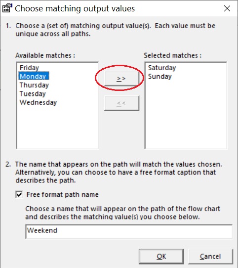
This dialog box has two sections. The first enables you to choose one or more matching values. When the script is executed, if any of your chosen values for the path match, the script continues execution on that path. The second section enables a free format label to be given to your set of matching values. For a path designated for weekend processing, the selection of Saturday and Sunday as matching values will label your path with "Saturday, Sunday". The second section enables you to use a label such as "Weekend", which might be more meaningful, as well as less space consuming on your chart.
The example shows a dialog box with the configuration described. The path will be executed if the result of executing the On Day node is Saturday or Sunday. The path itself will be labeled as "Weekend".
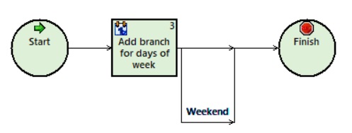
When the mouse is positioned above the arrow representing the path, the arrow rises to show focus and the Editor Window status bar shows the details of the path - its label and matching values.
When the script executes, if the On Day node returns anything other than Saturday or Sunday, the straight through (default) path is taken. In the example, nodes to be executed only on weekdays are inserted on the part of the default path arrow leaving the On Day node, but before where the Weekend Path rejoins the main flow. If there are already nodes which need to be moved into one or other of the paths, this can be achieved by using drag and drop or cut and paste as described above.
Editing a path
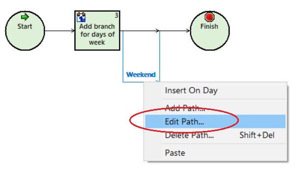
The attributes of a path (what it matches and the label it is given) are handled by the same dialog box used to add a path. The same mechanism is also used to launch the dialog box. If we follow the previous example where we set up a path for weekend processing, but decide to include Monday (as it is a Bank Holiday, for example), then we need to edit the path to change the match criteria. The figure below shows the context menu that appears when the Weekend path is right-clicked:
The Path configuration dialog box appears for the Weekend path. Monday can then be added to the path by highlighting it in the Available matches: pane and clicking the >> button. The label can also be changed appropriately.
Deleting a path
The same context menu that is used to add a path and edit a path can also be used to delete a path. Alternatively you can select the path by clicking the arrow and pressing <shift> Del.
Note: If a path is deleted ALL the nodes contained in that path until the path returns to the main flow will be deleted along with that path.
Undoing and redoing changes

All the changes described above, to do with working with nodes and paths, may be re-wound and re-applied. Each change made is noted in an undo buffer. The Undo toolbar button enables you to perform an Undo operation that rewinds the last change. This may be repeated for a sequence of changes.
Should you decide that you need to re-apply the change you have undone, you can use the Redo button on the standard toolbar. This may be repeated for the number of Undo operations that have been performed since the last update to the chart.
Passing information between nodes
As described earlier, the flowchart represents the flow of control through a chart. Where a node requires access to the information set up in a node, then script flow properties are used. Script flow properties can be added modified and deleted in the Flow Properties window.
For example, imagine a node that performs an IVR transaction to collect an account number. This account number could then be used in another database lookup node to read the customer's file. In this case the account number needs to be shared between the two nodes. To do this, a script property needs to be added.
Adding a script property
The Flow Properties window is invoked from the Menu toolbar by clicking View and selecting Properties Window from the drop-down list:
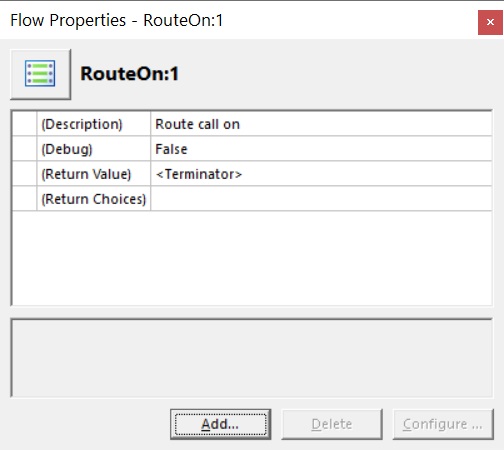
You will notice a number of reserved properties already configured.
To add a new property to pass the Account Id between nodes, click the Add... button. The Property Configuration wizard appears. In order to proceed, the name, data type and description need to be set:
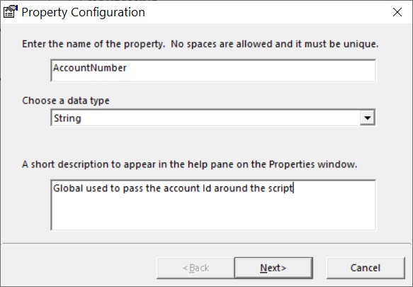
Name
This can be any text string that sensibly describes the property, but must be unique to the script.
Data Type
Choose from a drop down list. This includes string, numeric and time formats as well as rostrvm data types such as queues, devices and agent groups.
Description
This is a short description of the property's role, and appears at the bottom of the Properties window.
Click the Next> button to move on to the next screen:
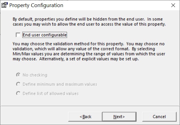
As we are using the property internally, we do not need to make it end-user configurable. You can therefore leave the End user configurable checkbox unchecked. Click the Next> button to move to the last frame:
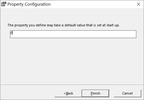
This frame allows a default or initial value to be configured. Depending on the data type selected, the data entry adapts accordingly. For rostrvm data types, a list appears containing only those values in the configuration that match the criteria, e.g. all the configured queues for the ACD Queue data type. In this case, however, we have selected the basic string data type, that allows simple string entry without checking.
Click Finish to close the wizard and add the new Account Number property to the Properties window:
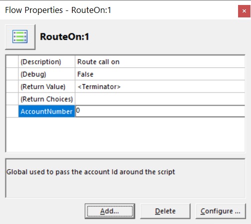
To remove an existing property highlight the entry to be removed and click the Delete button. To change an existing property, highlight the entry to be changed and click the Configure... button. This will e-open the Property Configuration wizard in order to change any details.
Using a global property in a node
This chart follows the example described above. An Account Id is collected from the caller and is stored in our global AccountNumber property. We now want to use this to decide call routing. The decision in this example is to be made through the OnProperty node.
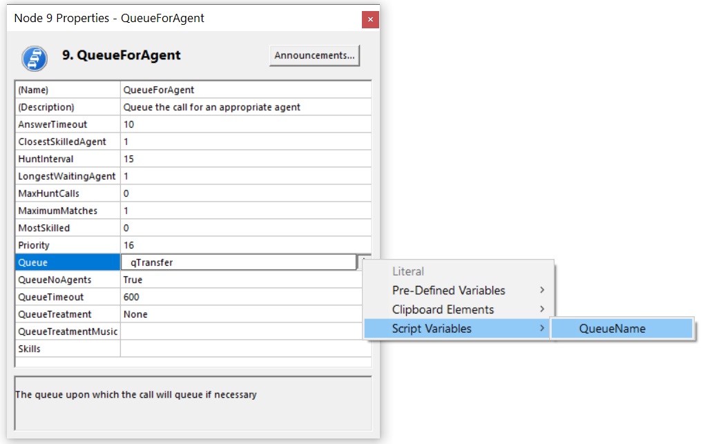
To do this, select the OnProperty node and double click it (or press Properties Window toolbar button). Next, select the Name property to display a data entry field and an extending arrow button to the right.
The Name input field allows you to type in an explicit Account Number. In this case, however, we want to use the AccountNumber global property. Select the extending arrow button to display a shortcut menu listing the CLIPboard elements and script properties. Only those script properties of the same data type as the AccountNumber property are presented:
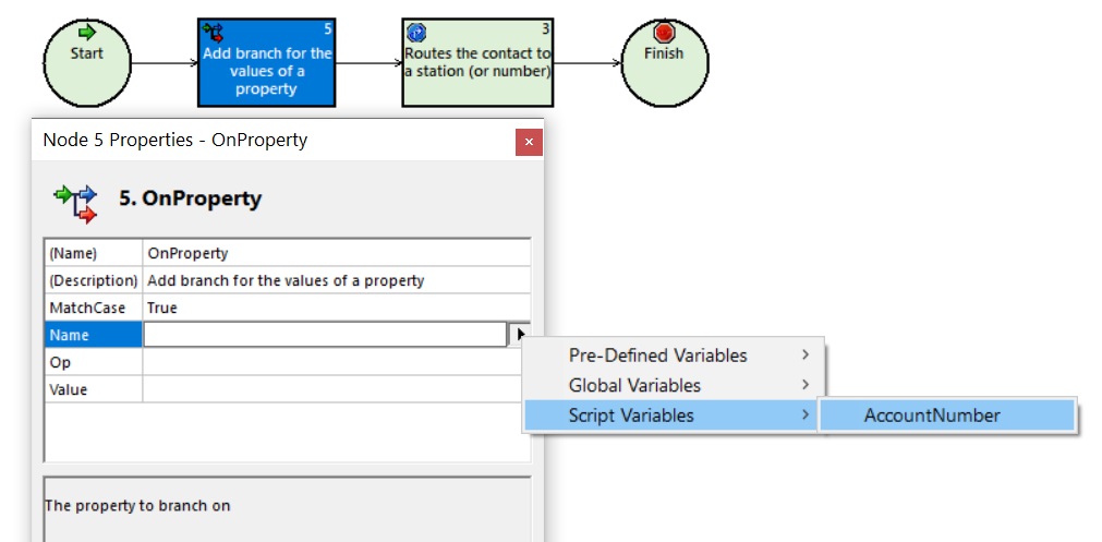
Select AccountNumber from the list to populate the Name field.
The Op and Value fields are optional.
| • | If they are both set then the OnProperty node will return TRUE or FALSE depending on the result of the operation. |
| • | If they are left blank then the OnProperty node will return the value of AccountNumber. |
Adding one or more paths after the node can then be used to check for TRUE or FALSE if Op and Value are set, or a real value if Op and Value are left blank.
Exposing script properties to the user
The script can be configured for the end user to see the properties of the script that can affect its behaviour, but not the script itself. This hides the complexity of the script from the user, and prevents any inadvertent damage that could be done if an inexperienced user had full access to the script.
This may be used where, for example, a script uses a default queue destination that may need to be changed from time to time. This is achieved by setting up script properties that are end-user configurable.
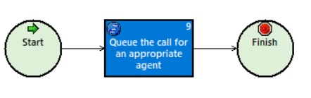
Consider the QueueForAgent node. This is used to place a call on a particular queue (specified in the node parameters) until an agent becomes available to take the call.
To allow the configured queue to be changed from the script properties, an end user configurable queue name property must be created. From the Script Properties window click the Add... button. The Property Configuration wizard appears.
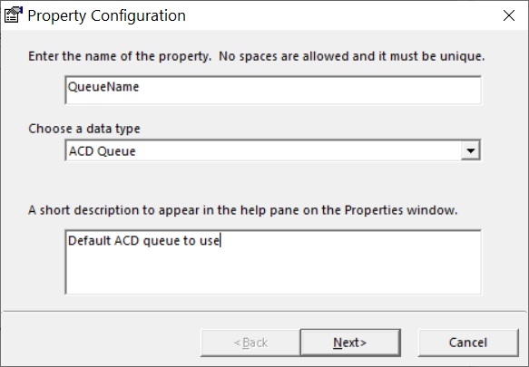
Set-up the name for the property, in this case QueueName, the data type, in this case ACD Queue, and the description that will appear against this property. Click Next> to display the next frame:
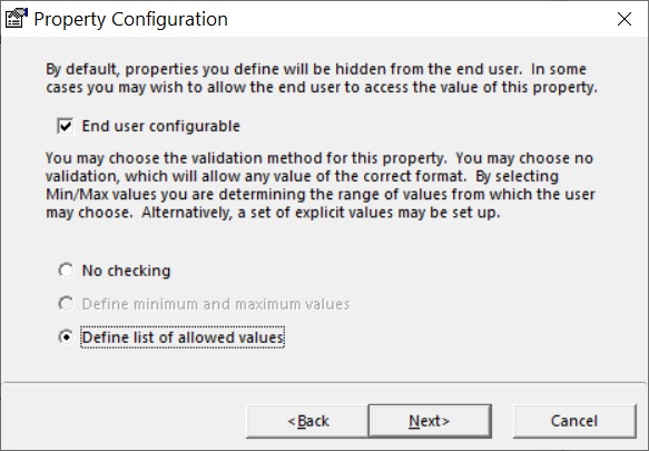
Ensure that the End user configurable checkbox is selected and also the Define list of allowed values option is selected (as shown). Click Next> to display the next frame:
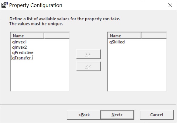
Select which queue devices the end user will be able to select, as shown. This allows a restricted list to be constructed to ensure that the user can only select from the queues that are valid for this script. Click Next> and an initial queue name can be selected as the default:
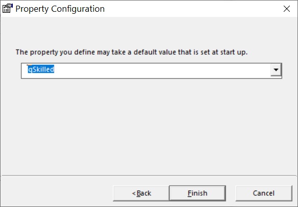
Click the Finish button to complete the global property definition.
When the script properties are viewed from within the script, they appear as follows:
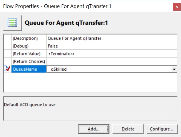
The red tick symbol to the left of the new QueueName property indicates that it is visible to the end-user. Note also that the name and description for the selected item, shown in the display panel at the bottom of the window, will appear in the end-user's property sheet.
The new QueueName property can now be used as a parameter of the QueueForAgent node in the script.
Properties can also be made global to all routing scripts by setting them from the Manager Queues and Routing page.
CLIPboard elements are used to move data with the call. These may be used internally within nodes in the script, or set up in the script to be passed to the nodes as input parameters, as script properties were in the preceding sections. The CLIPboard window is invoked from the Menu toolbar by clicking View and selecting CLIPboard Window from the drop-down list.:
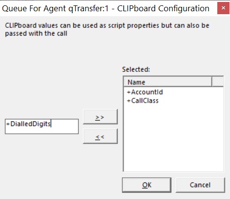
The text box enables a new name to be entered then added to the list of elements using the >> button. The << button is used to remove the selected item from the list. The element name is copied back to the text box where it may be amended for re-addition, or just deleted from the list. Once configured, CLIPboard elements may be passed as arguments to nodes.
Passing CLIPboard elements to a node
This procedure is the same as passing a script property to a node. Continuing with the example shown above, if we wish to use the standard CLIPboard variable +DialledDigits to decide the routing path, we need to first configure the element using the CLIPboard window. Type +DialledDigits in the text box and click >>, as shown above. The CLIPboard element now appears in the selection list for the OnProperty node.
Using CLIPboard to update Call details
Some CLIPboard elements can be used to update information associated with a call which is ultimately recorded in the MIS. Specifically, the following pre-defined items can be set:
+CallClassId - the call class associated with the call;
+DialledDigits - the dialled digits associated with the call;
+AcdQueue - the queue through which the call arrived.
These elements can be used to set call related items from within the CallDirector routing script.
Many of the nodes provide the ability to play an announcement to either the agent or the customer. You can change the announcement from a CallDirector script by selecting the Invex Announcement report from the appropriate node.
Invoking the Announcements Report
So for example, if in your CallDirector script you wish to apply treatment to the current call, and you wish to change the music to provide, insert the Apply treatment node, bring up the Properties page, and click the Announcements... button in the top right-hand corner.
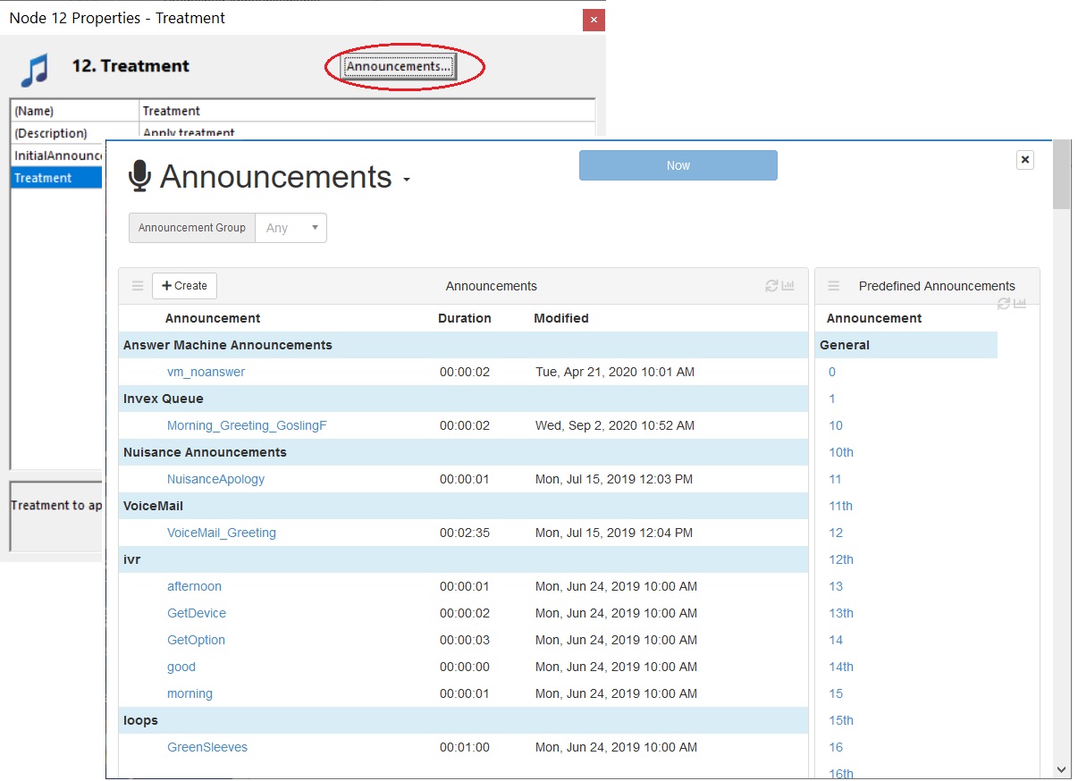
The rostrvm Invex Announcement configuration report is displayed. You would then set the Queue Music to be the file that you want to play in the Apply Treatment node.
Details of how to use this tool can be found in the Invex Announcements Configuration section.
Announcement nodes
The announcement tool can be launched from the following CallDirector Editor nodes:
Each script has two reserved properties visible in the Script Properties window, Debug and StopOnError. These properties cannot be deleted or configured but may be used to set special features within the script when it is run by CallDirector. They are only available to users with the Developer extensions installed.
Debug Property
Setting this property to True will cause in-built debug statements in the nodes to be written to the rostrvm log. However, setting this option will cause the log file to fill faster than it might have done otherwise. This may compromise the integrity and performance of the system if left in this state. Unless there is a problem with a script that requires tracing, it is advisable to leave this option as False.
StopOnError Property
Setting this property to True will cause the execution of the script to stop should a run time error be encountered within the script.